Recently, there has been a very healthy discussion on whether Moore’s law is still valid. While the arguments fly from both sides, there is one thing that everyone agrees on – chiplets are the solution to the need to constantly increase the functionality of SoC, while also reducing cost.
Whether you are building a 2.5D, 2.xD or 3D-IC system, you are facing a similar problem – packing more functionality inescapably leads to higher power density. While tools like the Anemoi Thermal Solver enable you to understand how heat from power dissipation moves through the system and helps you devise ways to better cool your system, the question of how to generate power for the whole system still remains.
Typically, this would be done in an Excel spreadsheet. In a classical 2D SoC this worked until a few technology nodes ago. Then we started getting uneven power densities leading to localized hot spots. This, in many cases, pushed the Power Spreadsheet to its limits – we need to consider multiple blocks, operating in different functional modes, and in many cases in different power management states. The only reason why spreadsheet still works for 2D SoC is simple – ownership of the design most likely lies within a single department.
In chiplet-based systems, this no longer works. The design of a fully packaged 3D-IC system has cross-departmental ownership, and may even span across companies – package design, SoC design, DRAM suppliers, and voltage regulator suppliers all participate in the design at the same time.
This presents interesting challenges in how to model a complete 3D-IC system. In this article, we will focus on power.
Modeling for the Complete 3D-IC System
Packing multiple chiplets in the same package has complicated the design of the power delivery tree significantly. In monolithic SoC, all power trees are typically off-package. Densely packed 3D-IC will need to share the same power source, which in some cases may be generated in-package with integrated voltage regulators, while in others may be shared with off-package components.
In either case, including all components, in-, and off-package is necessary to account for voltage level dependencies, correct regulator sizing, and regulator heat dissipation due to conversion losses.

In the case of monolithic SoC, we were able to get away with a single power limit, known as TDP. In a heterogeneously integrated 3D-IC system, a single number no longer has meaning – power sizing and heat dissipation vary too much across each chiplet’s mode of operation. This has led to the introduction of Scenario Design Power.
Typical spreadsheets are unable to handle the complexity of Scenario Design Power, which needs to be generated per supply and with consideration of the entire power tree.
Our PowerMeter tool takes it from where the spreadsheets break and take system power analysis to the next level. It incorporates system power models that support all components, with the flexibility to support from approximate to exact power data. It also includes full system connectivity support and a time-based scenario definition. This enables architects and designers unprecedented insight into their system’s power dissipation, energy consumption, current draw, and current ramp.

Understanding Power Overhead of Die-to-Die interfaces
As mentioned above, the cost and yield of advanced nodes drive die dissagration. It is a well-known fact that smaller dies will yield better, thus the overall die cost of a chiplet system is reduced. However, now chiplet dies need to communicate over die-to-die interfaces.
The UCIe interface, recently proposed by a consortium of companies, strives to standardize die-to-die interfaces. However, adding additional interfaces comes at the cost of increased energy consumption and power dissipation.
Understanding this additional overhead necessitates additional analysis. An IP provider will provide power metrics, typically defined as energy per bit transmitted. However, it is up to the chiplet system integrator to determine the final power consumption overhead. One easy way to do this is to guess what the interface bandwidth usage is. This is prone to errors, the magnitude of which would not be known until silicon comes back. Another would be to spend engineering time using a simulator, and interface models to determine actual power. This is difficult and the time investment makes this impractical when performing architectural analysis. A better way is to use a lightweight analyzer such as Anemoi Software’s SimInspector – just load a simulation dump into the tool and measure the data bus activity.
Thermal Coupling and Power Distribution Maps
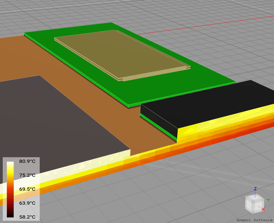
One term that gets a lot of attention these days is thermal coupling. In 3D-IC this term refers to the fact that heat from any chiplet in the package will dissipate into nearby chiplets. Thermal coupling considerations play an important role in the architecture and design of the 3D-IC.
This however requires a precise understanding of the spatial distribution of power dissipation within a chiplet – a CPU chiplet may heat an HBM chiplet beyond its limits; a hotspot on one chiplet may align with a hot spot on the chiplet above it; two UCIe interfaces facing each other may generate enough heat to exceed a maximum temperature limit.
The modeling solution to this problem is in detailed power distribution maps. They provide the spatial distribution of power across a chiplet’s die. With this information, thermal simulation software, such as Anemoi Thermal Solver, can simulate heat transfer in the 3D-IC. This enables architects and designers to view heat generation and heat dissipation.

Conclusion
The cost of designing large SoC in advanced nodes is driving the trend of disaggregation into chiplets. This trend has enabled the integration of multiple chiplets within the same package both in 2.5D configurations and more recently in 3D stacked configurations. The complexity of modeling power of this densely packed 3D-IC is driving the venerable Power Spreadsheet into extinction. More advanced tools are required to be able to handle the needs of modeling complete systems, spatially, in multiple scenarios.
Our PowerMeter tool is well positioned to handle this complexity with ease. Reach out to david@anemoisoftware.com for more information on how it can alleviate the pain of modeling 3D-IC systems.