Thermal problems in semiconductor electronic systems often go unnoticed and cause failures. Although thermal problems can be understood and avoided by proper design, it takes time and money to build a new system with improved thermal performance. The good news is that there are many thermal analysis tools available that can help you simulate these issues before they occur. These tools include analytic calculations, empirical analysis, and computational modeling.
With today’s need to manage energy consumption, avoid failure due to component overheating, and avoid costly overdesign, it is necessary to harness the full potential of thermal modeling tools for semiconductor electronics systems. Semiconductor electronic systems, in this case, refer to multiple PCB assemblies within an enclosure, a single board with multiple heat-producing ICs, or even a single IC in a package, mounted on a substrate.
To design for the best thermal performance and avoid the issues previously mentioned, thermal design optimization techniques are needed to manage how heat flows in an electronic system. This article will present an overview of some of the thermal analysis techniques specific to managing and optimizing heat transfer for high-density electronics systems.
Thermal Analysis Techniques
To analyze simple systems with a single active source producing heat on a substrate in a well-understood environment is quite straightforward by utilizing the concepts of thermal resistance and capacitance. A designer can use thermal resistance to estimate the junction temperature of the device either in a steady state or combine the resistance concept with capacitance and model the transient response as well.
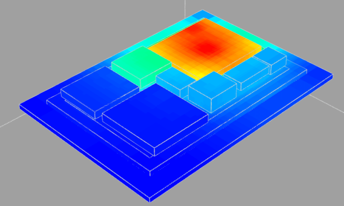
The difficulty in thermal analysis quickly compounds when adding just a few (> four components) more heat-producing devices to the model and trying to fit them all in a small space. The thermal coupling between multiple heat-producing devices can be a significant contributor to each device’s individual temperature and this is very complex to model.
Engineers will model the heat transfer similar to how electronic circuit designers model voltage and current in electronics systems except replace these concepts with temperature and power. Borrowing concepts of resistance and capacitance from electronics and transforming them into thermal and power concepts is the basis of many custom sprawling spreadsheets populated with thermal resistances that model all thermal relationships between all nodes of interest. These are well-understood techniques that the reader can investigate in many thermal engineering textbooks, but will not be fully described here.
Many engineers will build complex spreadsheets, ostensibly based on actual measurements, made by turning on one device at a time and recording the heat transfer to all the other points, and summing these. The assumption is that the principle of superposition would hold and a simple linear analysis would give a reasonable idea about how heat transfer would conclude when all devices are running at the same time. This spreadsheet methodology lacks the muscle to lift all but the easiest thermal modeling tasks and leaves the system designer looking for more potent modeling methods.
The CFD Simulator
The next level up in thermal modeling is usually looking for the appropriate 3D model-based CFD (computational fluid dynamics) simulator that can simulate any 3D geometry under any thermal condition and model steady-state and transient cases as well. Depending on the modeling need, the CFD simulator can model all thermal solid-to-solid and solid-to-fluid heat transfer interactions as long as the correct options are selected.
The CFD simulator approach is not a path for the faint of heart and not a natural tool workflow for electronics engineers who are struggling to architect a system without thermal problems (as it is not their main area of expertise). The CFD tools require the following to be an effective strategy in modeling heat transfer:
- Proficiency in CAD tools
- Mechanical model preparation for the simulator (the model can’t be overly detailed otherwise the simulations will not complete quickly enough to be useful and can’t be overly simple otherwise the results will be inaccurate. It is quite a common requirement for the simulation engineer to judiciously “de-feature” an existing mechanical assembly so that the original heat transfer details are not lost.)
- Assign materials and boundary conditions to match the conditions of interest
- Reasonably fast iteration so that intelligent tradeoffs can be made
Getting past these requirements is typically an insurmountable task for most electronic system designers (who may be chip designers or electronic assembly designers) and they have to rely on their mechanical/package engineer colleagues, who have mastered these tools, to build their thermal models for them. Therein lies the downside of pursuing the CFD approach too early in the design process.
The system designers are not CFD experts and therefore reliant on the company’s lonely overloaded CFD expert with the one or two expensive licenses for the tool. The CFD experts are typically so overloaded with requests in the companies that have them that many jobs can be in the queue for weeks and sharing the results is not typically systematic or robust across the full design.

Remember, system design details have to be handed off to an engineer from a different discipline and there is always some information “lost in translation” between electronics engineers and packaging engineers who will run the CFD tool. Additionally, this situation hardly lends itself to an iterative optimization process or encourages the exploration of different design architectures. Ideally, the original system designers should be given the power to optimize their designs for heat transfer in a way that is easy.
Early Architectural Experimentation and Feasibility Analysis
As is evident from the above there is a need for something that can handle thermal coupling modeling between many components across a system that is more powerful than linear analysis of a spreadsheet but not so complicated that one needs to dedicate all their engineering hours to learning the nuances of using an advanced CFD simulator tool to get started modeling.
This process has to be accessible to electrical engineers and electronic system designers, meaning training to a useful skill level must be extremely quick. The modeling process should encourage collaboration between team members and make optimization and design iteration easy.
One possibility is to work with the team at Anemoi Software that has built a thermal solver tool that is primarily based on the conduction method of heat transfer and therefore lends itself well to high-density packages with many ICs in all types of packages. It is a cloud-based tool that comes with a minimum of three licenses, so users are encouraged to share designs and collaborate between their accounts easily. The solver is optimized to run small and very large designs with thousands of components extremely quickly (in comparison to a fully meshed CFD design). The quick solving speed is critical to sparking the designers’ creative juices to try different architectures. There are some tradeoffs in accuracy using these tools since the thermal solving is not a fully meshed CFD simulation. These can be discussed in detail with the Anemoi team.
Other Methods For Thermal Analysis Modeling
There is another method that works really well when attempting to model heat transfer in an electronic system and like the methods already discussed it has its drawbacks. This is also probably the most common method employed (although this author doesn’t have the data to back this up) and that is to build a prototype of the model and measure it using thermal imaging (IR scan) or populate the prototype with thermal sensors or thermocouples to measure the actual temperature at all locations of interest.
The disadvantage of this approach is the prototype has to be built and measured, and that takes resources and time but the accuracy of this approach is the highest as there is no estimating of heat transfer, only building and directly measuring and then iterating on optimizing thermal profile of the prototype. The results could be fed into a spreadsheet or model or once a satisfactory thermal design is attained that then becomes the final design. This approach can be used to calibrate a software model as well and then used as a basis for future designs.
Conclusion
Hopefully, the reader found this short summary on thermal modeling of semiconductor electronics systems useful. For more information please contact us at info@anemoisoftware.com. The team at Anemoi Software can provide easy-to-use thermal modeling tools, support, design services, and correlation measurement services for electronic systems of any type, including chiplet-based ones.