
With each passing year, emerging growth application areas such as Automotive, Cloud Computing, Industrial Automation, and Telecom (5G) Infrastructure are garnering more attention. Although the application segments are different, there is a commonality in how voltage conversion and power distribution are achieved at the system level. System demands are becoming more important to reduce an effective carbon footprint. As a result, a new 48V Ecosystem is being developed and deployed to meet various objectives, including very high efficiency. Whether its power supplies, computing elements or memory blocks, semiconductors are at the crux of the solution in meeting these demands. The focus of this paper is to discuss market and technology trends in each of these application areas and share thoughts on how innovative power packaging platforms are trying to meet both electrical and thermal requirements.
Automotive
Most luxury vehicles today run several millions of lines of code networking up to 100 electronic control units (ECUs) [1]. The higher the degree of electrification, comfort features, and advanced driver assistance systems (ADAS) in a car, the higher the need for the total power budget. As some of these advanced features, offered today in luxury cars, migrate to standard cars, cost becomes imperative without sacrificing the efficiency of the electrical power system. Today’s existing vehicle power tree is powered directly from a 12V battery to the mechanical auxiliary loads (typically < 5-7 kW) such as water and oil pumps, climate compressor, active roll control, headlights, and taillights. These loads, combined with additional requirements to satisfy stricter emissions norms from Corporate Average Fuel Economy (CAFE) standards and power-hungry ADAS systems, makes it challenging to improve efficiency. Though the car original equipment manufacturers (OEMs) have been replacing mechanically driven components with electrical counterparts for many years, there is a further need for newer architectures such as the 48V system. In the short-term, OEMs and their tier-one (Tier1) suppliers may opt for dual architectures (12V and 48V) until a permanent shift to a 48V power net occurs in the future.
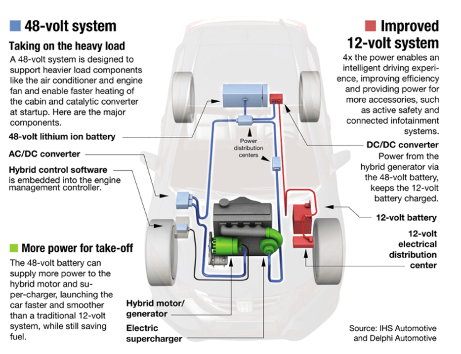
Automotive OEMs and Tier1s have introduced several mild hybrid electric vehicle (MHEV) solutions recently. For example, Audi has introduced a new belt alternator system (BAS) with a capacity of 12 kW to powerup its mild hybrid cars while also implementing a DC-DC converter for the legacy 12V systems [2]. Similarly, Daimler has introduced an integrated starter generator (ISG) for its S-class with a capacity of up to 16 kW [2]. Daimler, like Audi, is also implementing a DC-DC converter block for the legacy 12V loads. Tier1 supplier Valeo introduced its eCruise4u platform, combining automated driving and a 48V hybrid system. One of the products of this platform, e4AWD smartly combines an integrated belt starter generator (iBSG) and electric rear axle drive (eRAD), adding 22 kW capacity to its MHEV system and thereby reducing fuel consumption by 17%. Delphi, another automotive Tier1, has introduced a 48V hybrid system, as shown in Figure 1, which includes an e-supercharger which improves fuel efficiency by 15%. This e-supercharger system may also use the dynamic skip fire (DSF) cylinder deactivation concept, reducing CO2 emissions by 13% [2].
The shift to a 48V power net enables several benefits such as wiring harness cross-section and weight reduction, resulting in lighter vehicles and emission reduction. While the electrification of mechanical components in steering racks, comfort and convenience features, and other systems helps, mild hybridization using motors (< 25kW) will have significant tangible benefits. One estimate [1] suggests that MHEVs will reduce CO2 emissions by 15%, which amounts roughly to 70% of the benefit at roughly 30% of the full hybrid system cost. Obviously, willingness to pay an additional $1500 or so for a mild hybrid compared to about $4500 for a full hybrid is expected to create an impetus for MHEV vehicle growth. Additionally, the 48V power net would also serve to provide system readiness (point of load control) for future applications in both vehicle-to-everything (V2X) connectivity and ADAS. With the mass rollout of Level 3 to 5 self-driving vehicles expected in the next decade, the power requirements for ADAS systems will only surge. Current Level 2 capability needs power wattages in the order of 1kW, whereas Level 4/Level 5 systems would need 10x more power. This, along with the cost and emission benefits, 48V MHEV systems are seen as gateways to the expanding EV market.
Cloud Computing
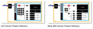
Today, more than seven million data centers around the world are needed to manage more than 2.5 quintillion bytes of data, created each day from personal and business uses. Of the 44 zettabytes (44 trillion gigabytes) data that has been created to date, 90% of the data was created in the last 2 years [3]. Due to the advent of over-the-top (OTT) streaming services, 5G, Internet of Things (IoT), and social media, big data is expected to morph cloud and edge datacenter markets significantly. A typical data center would offer services such as data storage, processing, networking, and distribution. To manage these services, operators require tremendous amounts of power on the order of several 100s of MW. As much as 40% of the operating costs of the data center comes from the energy needed to power and cool racks of servers [4]. Power Usage Effectiveness (PUE) and Total Cost of Ownership (TCO) are two very important metrics for data center operators to reduce costs and improve utilization. On average, approximately 30-35% of the power is wasted in the conversion from the AC grid to the microprocessors of an individual server. Along this power path, losses can be reduced mainly in three areas – universal power supply (UPS, grid-to-data center), server rack power supply, and individual server power supplies. Until a few years ago, data centers were designed for 4 to 5kW per rack and now they are up to 10kW per rack. Increasing rack power density up to 30kW or more will be the trend in the future [5]. As a result, smaller and efficient power supplies are needed as they can improve the PUE, resulting in greater server density and additional revenue per foot of floor space ($/ft).
5G Infrastructure
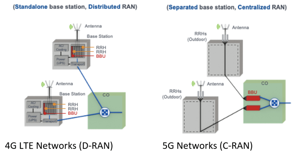
To address shortcomings of the current 4G network, 5G networks should be able to handle large traffic (radio over ethernet) and large capacity (IoT, connection density and bandwidth), while being very reliable (edge computing, latency). The key changes include a new spectrum, a greater number of sites, and multi-access edge computing. Currently, the theoretical limit of the transmission bandwidth of the 4G LTE network is about 150 Mbps, which cannot meet the requirements of 5G. To achieve higher bandwidth, a 5G network uses a higher frequency C-band. Additionally, massive multiple-input multiple-output (MIMO) technology is the key to improve throughput. As indicated in Figure 3, in terms of topology, existing 4G networks favor a distributed radio access network (DRAN) architecture where the antenna, remote radio head (RRH), and baseband unit (BBU) are separate. However, 5G networks tend to favor a centralized or cloud (C-RAN) distribution to consolidate baseband functions, moving them from the cell sites to a centralized location. In 5G networks, it is expected that the RRH and antenna are integrated while the pool of BBUs is at the edge site. BBU pools (or core network) share the same physical infrastructure, including network equipment such as routers, physical infrastructure, electricity, and cooling systems. However, a greater number of sites and higher computing requirements will further increase network energy consumption.
According to telecom operators, the power consumption of one band 5G equipment maybe 350% that of 4G with a similar configuration [6]. A 5G BBU consumes about 300W while an RRU consumes about 900W at a 30% load (peak is ~1.4 kW). As more frequency bands are added in the next 3 years, the peak power consumption will increase to about 14 kW. Beyond that, with the addition of mm-wave, the peak power may increase up to 20 kW [6]. Though existing 4G telecom power supplies are designed at -48V, these power supply units are not compatible with the 5G needs. The absolute power losses from the power supply cable in 4G system tend to be smaller as the power requirements are on the order of 1 kW. However, absolute losses for the same cable length are higher in a 5G system, resulting in a higher voltage drop along the cable. As with most power supplies, once the voltage drops below a threshold ‘low output voltage’, the power supply shuts off. To mitigate this problem, power supply designers may use an additional DC-DC converter to boost the voltage levels to around -57V for effective operation [6]. As a result, the increased power consumption of the 5G network brings challenges for the entire power supply system.
The 48V Impact on Semiconductors
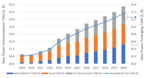
Consistent with the market requirements discussed above, there are significant increases in new market opportunities for semiconductor suppliers. In the automotive sector, the mild hybrid segment is approximately 1.5% to 2% of the total production today; however, by end of the decade, it is expected to grow to about 15%. Consequently, power semiconductor content per car is expected to increase approximately $75/vehicle due to the adoption of mild hybrid systems. Similarly, with the migration to 48V power net in hyper-scale and 5G data centers, the power device bill of material (BOM) is set to increase by about $40. Finally, due to 5G infrastructure deployment, both cabinet and blade power supply requirements will increase the need for power transistors. The 48V Ecosystem presents an opportunity for semiconductor suppliers to apply synergies among these application segments. From the overall new market opportunity, Figure 4 outlines the key application segments and respective growth prospects. Whether its 48V in automotive and cloud computing or -57V in 5G power supplies, the underlying assembly, and test business is also set to grow significantly in the next decade.
Technology Trends that Need Power Packaging
Considering the application trends discussed thus far, the common theme is that customers need power semiconductor solutions that are highly efficient, occupy less space, and very reliable. For over 30 years, power conversion efficiency and cost ($/W) has shown steady improvement due to innovations in silicon (Si) Power MOSFET technologies, power packages and circuit topologies. Though Si has been the workhorse, figures of merit (Ron x Qg, Ron x Qoss) have reached the theoretical bounds of Si. Newer material systems, such as gallium nitride (GaN), have entered the market space offering better performance. However, to realize system benefits, packaging technologies must not limit achievable electrical and thermal benefits. Historically, power device packaging has evolved from through-hole packages such as TO-247 and TO-220 with long leads to surface mount components with leads such as D2PAK, DPAK, SO-8. Further, leaded packages have been replaced with lead-less surface mount options such as TO leadless (TOLL) and PQFN. With the growing need for increased power density and highly reliable solutions, the packaging industry must deliver innovative options to meet the emerging trends. Customers may need solutions that offer effective thermal management via dual-side cooling, chip-scale packaging, and multi-die integration to reduce parasitics. However, there will be trade-offs in terms of cost, performance, and reliability.
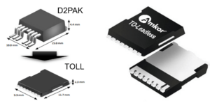
An automotive use case provides a helpful example. A belt starter generator application requires about 12kW, where the intermediate rail from the power system is at 48V. The inverter stage to power up the motor uses MOSFETs rated higher than 48V while the currents are higher than 500A. Generally, multiple MOSFETs are paralleled to meet the full power requirement. In the power stage, where devices are paralleled in both high-side and low-side legs for a full 3-phase implementation, printed circuit board (PCB) space is premium especially when the power stage is integrated within the motor itself. D2PAK 7L, a common package used in such an application and wattage cases, has a package size of 15x10x4.4 mm. However, when several packages are required for a power stage, space becomes premium. Similar to D2PAK, TOLL (11.7 x 9.9 x 2.3 mm) is also a molded package that has been optimized for high power and high-reliability applications. But TOLL (Figure 5) offers 30% smaller dimensions and > 50% smaller form-fit allowing compact designs and high current capability and low thermal resistance (RthJC). Another critical aspect to note is evolving mission profiles for automotive semiconductors which mandates higher levels of reliability at the board level.
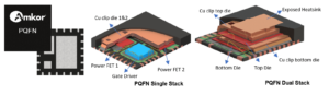
Different power requirements exist for server power supplies in cloud and edge data centers, supply power to CPU cores, DDR memory and point of loads such as stand-by rails, fans, and drivers. For applications where distributed point of load (POL) architectures are preferred, a power block or power stage in a single package is an optimal choice. With flexibility in integration, packages such as PQFN (Figure 6) are becoming more popular. PQFN packages offer the scope to improve die to package ratio and exposed heatsink, resulting in higher power density for server power supplies. Larger body size PQFNs offer integration of multiple FETs (power block) via die stacking using copper (Cu) clip technology as shown in the PQFN dual-stack picture in Figure 6. Another option is to integrate a gate driver with the high-side and low-side power FETs (power stage) to realize smart power applications such as DrMOS. This is shown as a single stack option in Figure 6. Additionally, PQFNs are used in applications such as telecom infrastructure, baseband boards and DC-DC converters.

Power Packaging Trends for the 48V Ecosystem
As one of the leading outsourced assembly and test (OSAT) suppliers, Amkor has a diverse portfolio to offer in the emerging 48V Ecosystem. This strong position stems from a global presence and partnerships with top semiconductor suppliers. Power packaging is supported by two different factory locations – Amkor Malaysia (ATM) and Amkor Japan Fukui (JFI). Broadly, several value-creating features and technology differentiators are offered such as advanced lead frame technology (XDLF), copper clip interconnects, aluminum (Al) wedge bonding, and space-saving surface-mount, flat lead designs. As discussed earlier, power packaging has evolved from through-hole (TO) type to surface mount (SMD) packages. Recently, SMD leadless packages such as TOLL have been getting more attention. These packages are fully qualified to the Automotive Electronics Council’s AEC-Q101 standards with sufficient power cycling and temp cycling on board (TCoB) capabilities. However, limitations may arise on the reliability, current capability, or package patristics front. As a result, a few emerging packaging ideas are discussed below to meet the requirements of the new 48V Ecosystem power packaging market.
Based on IPC International’s IPC-9701 standard, TOLL can fulfill the standard requirements of 1000 cycles (onboard) depending on die size and thickness. However, designers who require a high die to package ratio and/or extended reliability may find it challenging. Typical board substrates used are FR4, Cu-based intermetallic substrates (IMS), or Al-based IMS. However, when a substrate option such as Al-based IMS is considered, the board level reliability issues of TOLL may further exasperate due to vastly different thermal coefficients. The mismatch between the Cu leadframe and Al-IMS will lead to higher stress on the solder material, causing solder fatigue and cracks. By employing a gull-wing approach in the TOLL design (see Figure 7), TOLG can significantly improve the reliability levels while still offering comparable thermal and electrical performance. The flexibility of the gullwing design offers a marked improvement in reliability performance. This becomes imperative due to changing mission profiles in end-user segments, where extended stress and reliability have become a key system requirement.
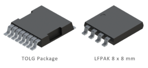
Alternatively, as datacenter server farms migrate to 48V architectures, power density requirements to address PUE will be a key concern. The trends of improving power device figures of merit can only take designers so far. Newer packages, such as the LFPAK (see Figure 7) in bigger body sizes, like 8 x 8 mm, will be a great addition. Compared to a traditional 7L D2PAK, an 8×8-mm LFPAK is 60% smaller in mechanical dimensions but also 80% lower in volume. In terms of interconnect technologies, wire bonds determine the current-carrying capabilities of current generation power products. In the case of the D2PAK, the maximum diameter of the bond wires used is 20 mil. However, in the LFPAK 8 x 8 mm, by using copper clip technology for interconnects, the current-carrying capability will be much higher. Parasitic resistances and inductances from the wire bonds are minimized significantly with the clip technologies. This packaging approach alleviates some of the concerns for the achievable power densities.
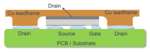
In server architectures, fast-transient response times demanded by microprocessors have led to the adoption of POL converters and voltage regulators. The parasitic impedances of conventional power electronic packages, operating at frequencies over 1 MHz, are not adequate. In this regard, Amkor is exploring chip-scale packaging for power transistors – the PowerCSP™ package – as shown in Figure 8. This innovative concept is a leadframe-based chip-scale packaging, allowing for double-side cooling where the top/leadframe side can be connected to the heat sink or water cooling. The bottom side of the package can be mounted to the PCB using thermal vias and power Cu layers. Key advantages of the PowerCSP concept are that it eliminates wire bonds and/or Cu clips, resulting in low parasitic resistances and stray inductances thereby reducing conduction losses and switching losses, respectively. Additionally, the reduced parasitic inductance of PowerCSP helps in achieving higher switching frequencies and power densities. Compared to plastic power packages such as the PQFN or LFPAK, the PowerCSP design can be constructed with a simplified process flow thereby reducing possible sources for reliability concerns as well. Furthermore, PowerCSP packaging would provide a gateway for multi-die integration to realize converter-in-package type solutions.
Summary
Driven by environmental, economic, and social factors, the demand for sophisticated power electronics solutions, reducing the total cost of ownership, will increase. The emerging 48V Ecosystem provides a gateway for the power semiconductor packaging segment to thrive. Although power packaging is mature, there is a need for improvements to meet emerging trends. Whether improving die to package ratio, reducing package parasitics or increasing current-carrying capable interconnects, an extensive existing portfolio and innovative new approaches can provide the solutions. This requires strong technology know-how and well-established customer partnerships to deliver on these challenges. Amkor not only can satisfy these requirements but also has the financial and technical strength to make significant investments in equipment and facilities and provide long-term support for its automotive and other power customers.
Author: Ajay Sattu, Sr Manager, Automotive Strategic Marketing
References:
[1]. Manish Menon et al, “48V Architecture: A Cost-effective Proposition for OEMs to Meet Growing Emission Norms”, Aug 14th, 2018
[2]. Automotive IQ et al, “The rise of 48V technology – an Automotive IQ eBook”, Aug 14th, 2018
[3]. Branka Vuleta et al, “How much data is created every day?”, Jan 30th, 2020
[4]. Energy Innovation et al, “How much energy do datacenters really use?”, Mar 17th, 2020
[5]. wiwynn et al, “48V: An improved Power delivery system for Data Centers”, Jun 2017
[6]. Global ICT Energy Efficiency Summit et al, “5G Telecom Power Target Network”, Oct 2019
PowerCSP™ is a trademark of Amkor Technology, Inc.
© 2020, Amkor Technology, Inc. All rights reserved.