
Since it first appeared several years ago, IFTLE has been a big-time proponent of pre-applied non-conductive film (NCF) combined with thermal compression bonding (TCB) for fine-pitch bump interconnection. This technology is now being used in mass production for 3D memory die stacking DRAM (3DS DRAM) and high bandwidth memory (HBM) and appears to have become entrenched as technology-of-choice for this high-density, high- end packaging solution.
Hitachi Chemical – low-loss NCF
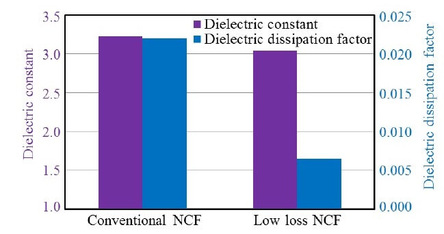
During a presentation at the recently held 69th ECTC, recently held in Las Vegas, Hitachi Chemical pointed out that the 5G era, just around the corner, will be achieving 10 Gbps or higher telecommunication speed. Such RF speeds will be enabled by NCF with lower loss dissipation factor (Df) values (Figure 1). The Df of a conventional epoxy-based NCF is 0.02 vs their newly developed NCF which is 0.006.
Assembly results of the low-loss NCF is summarized in Figure 1. In the lamination process, the NCF filled in between the bumps without void, and dicing occurred without delamination of the NCF or die cracking. The assembled specimen was post-cured at 175°C for 2 h.
The assembled package with the new low Df NCF showed no failures over 1000 TCT (thermal cycling test) between 25 and 125°C.
LG Chemical – Laser-Assisted TCB
Also at ECTC, LG Chemical R&D and co-authors from several Korean institutes and universities presented their early work on laser-assisted compression bonding, which they call laser assisted bonding with compression (LABC).
LABC bonding and NCF were developed to increase the throughput of typical NCF TCB. Test chips with 27K 30μm pitch bumps were used to verify the process flow. The effects of the laser power on the joints’ quality after the LABC bonding process were investigated and compared with the joints formed by standard TCB technology.
To increase the throughput, the bonding procedure was divided into two-steps, pre-bonding and post-bonding: Prebonding for the attachment of the devices on a substrate and post-bonding for the compression and laser irradiation process, as shown in Figure 2.
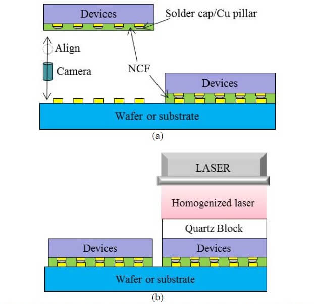
The film was laminated on the bumped wafer by a vacuum laminator after cover film peel-off. Proper vacuum
lamination temperature, pressure and time were applied to prevent air entrapment around the bumps and dicing lines. After the lamination processes, the base film was peeled-off without delamination.
To implement the LABC technology and high throughput, they designed and manufactured pre-bonder and post -bonder equipment. The pre-bonder is composed of two heads in one gantry. It bonds the NCF-laminated die to a substrate wafer at low temperature and pressure. The post bonder consists of a laser source, optics parts for the laser irradiation, and parts for applying high bonding pressure. It bonds the pre-bonded die on a substrate wafer using laser and pressure. When the dies are bonded, it is pressurized by using three piezo actuators.

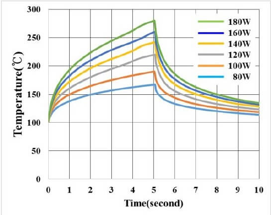
When the bonding force is applied, three force sensors precisely control the bonding pressure while piezo actuators measure the actual pressure in real time. The irradiated laser beam then passes through a transparent quartz tool at the bottom of the pressure module and reaches the die to be bonded. Laser time and power are used to control the solder reflow process. Solder joints formed at different power settings are compared to a TCB bond in the figure below. The temperature of the stages in the pre-bonder and post-bonder were 90°C. The laser power was varied from 80W to 180W. The bonding force was 70N.
Variations of measured temperature with laser power are shown in Figure 3.
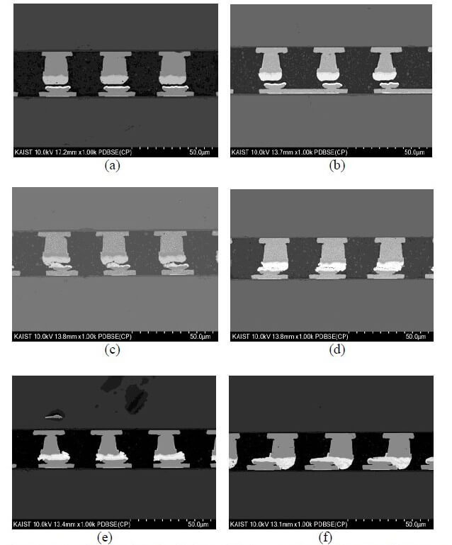
Bonds formed at the listed power settings are shown in Figure 4. Good bonds were formed at higher power settings like (e) or higher pressures.
Scanning acoustic tomography (SAT) images were taken of the test vehicles before and after the processing to check for voids in the NCF after the LABC bonding process.
Although these are early-stage results and are certainly not optimized, these results appear good enough to warrant further research in this area.
For all the latest in Advanced Packaging stay linked to IFTLE………………………………………..


