Few songs capture the feeling of a long-awaited breakthrough better than the Beatles’ Here Comes the Sun. The song is about the relief of light finally arriving after a long winter.
Something similar is happening in high-speed networking. As AI and other data-intensive workloads continue to increase the amount of information that must move between processors, switches, and accelerators, optical links are moving closer to the electronics that generate and consume that data.
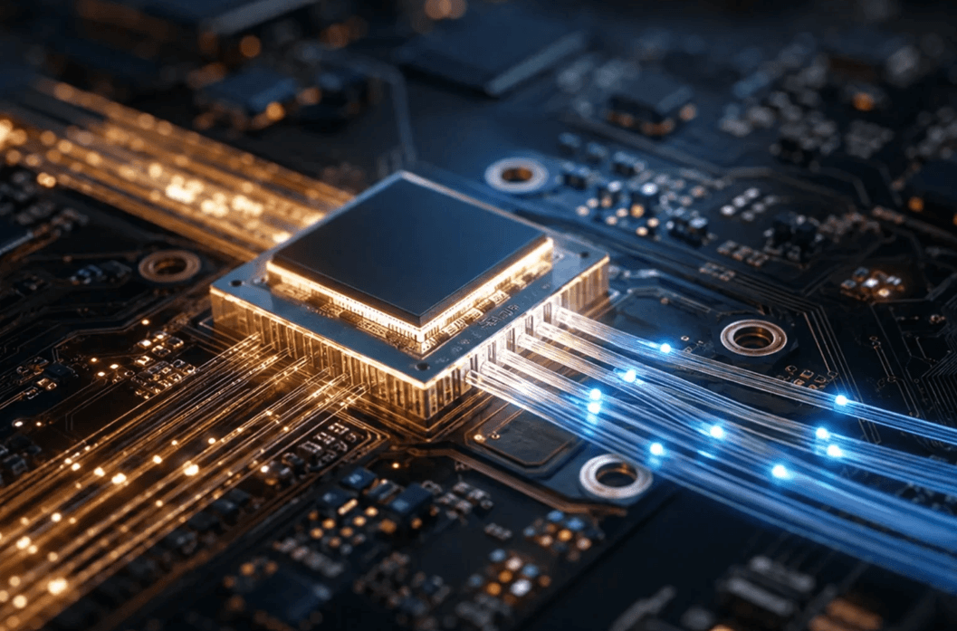
Co-Packaged Optics (CPO) is emerging as one of the approaches being developed to address this challenge. The basic idea is straightforward: move optical communication closer to the switching or computing silicon, reduce the distance that high-speed electrical signals need to travel, and integrate photonic and electronic functions more closely.
The idea itself is not new. What is changing is the combination of technology, bandwidth requirements, and manufacturing capabilities that is making CPO increasingly relevant.
In this first part of our three-part series, we look at how optics have moved progressively closer to the chip, why CPO has taken so long to mature, and why manufacturing flexibility may become just as important as photonic performance as the technology moves toward volume production.
Come Together: The Goal of Optoelectronic Integration
As AI, cloud computing, and other data-intensive applications scale, moving data can become a significant constraint on overall system performance and energy efficiency.
At very high data rates, electrical signals travelling through copper traces experience increasing attenuation and signal-integrity challenges. Maintaining signal quality over longer electrical paths can require additional signal-conditioning circuitry and power.
The basic goal of optoelectronic integration is therefore not to replace every electrical connection with an optical one. It is to shorten the distance that high-speed electrical signals need to travel and convert between electrical and optical domains closer to the devices that generate and receive the data.
This can help enable:
- greater bandwidth and bandwidth density
- lower electrical interconnect power
- longer optical transmission reach
Co-Packaged Optics takes this approach further by placing the optical engine close to the electronic switching or computing device. Instead of keeping the optical transceiver at the front panel, the electrical and optical functions become much more closely integrated.
The Long and Winding Road Part 1: Moving Optics Closer
The development of optical interconnects can be viewed as a gradual movement of the optical conversion point toward the processor or switch ASIC.
Figure 1 tells the story: optics are moving closer to the action. Each generation shortens the copper path between the switch ASIC and the point where electrical signals become light.
Pluggable Optics
Optical transceivers are located at the front panel. Electrical signals therefore have to travel from the ASIC across the package and circuit board before reaching the optical interface.
On-Board Optics
The optical engines move onto the circuit board, reducing the length of the high-speed electrical connection.
Near-Packaged Optics
The optical engines are positioned even closer to the ASIC, further shortening the electrical path.
Co-Packaged Optics
The optical and electronic functions are integrated within the same package, minimizing the remaining high-speed electrical distance.
The closer optics move to the electronics, the more attractive the architecture can become from a bandwidth-density and electrical-I/O perspective. But there is an important trade-off: integration becomes significantly more complicated.
And that is where the CPO story gets interesting.

Help! — CPO’s Biggest Challenges
Moving optics closer to an ASIC may solve one problem while creating several others.
Thermal Management and Laser Placement
Switch ASICs can generate substantial heat, while many photonic components are temperature-sensitive. Bringing these technologies together therefore creates demanding thermal-management requirements.
Mitigating this thermal bottleneck requires co-designing the optical engine alongside 2.5D and 3D Heterogeneous Integration (HI) packaging, leveraging advanced thermal interface materials (TIMs) or direct microfluidic cooling to pull heat away from temperature-sensitive silicon photonic devices.
The laser source presents an additional integration question. Depending on the architecture, lasers may be integrated with the photonic engine or located externally, with light delivered to the package through optical fibers. The choice involves factors such as temperature, reliability, and integration compatibility.
Fiber Attachment and Optical Alignment
CPO packages may require large numbers of optical connections within a very limited space. Maintaining low optical coupling losses therefore depends on accurate and repeatable alignment between fibers, photonic components, and other optical structures.
Recent work in 3D photonic packaging reflects the range of coupling concepts being investigated, including edge couplers, grating couplers, freeform couplers, evanescent couplers, and other approaches. [8]
Manufacturing, Yield, and Testing
CPO combines electronic and photonic components in a tightly integrated assembly. That increases the number of interfaces and process steps that must work reliably together.
Testing therefore becomes multidimensional: electrical, optical, mechanical, and thermal behavior all matter. Manufacturing yield is equally important because a defect in one integrated component can affect the performance of the overall package.
Serviceability
The operational model also changes. A conventional pluggable transceiver can be removed and replaced independently. A co-packaged optical engine is much more tightly integrated with the surrounding electronics, making fault isolation and field maintenance far more complex. To address this, industry standards are increasingly favoring modular optical engines designed as Field Replaceable Units (FRUs), balancing high integration density with realistic data center maintenance requirements.
Standards and Supply Chain
CPO also depends on the interaction of multiple technologies and suppliers, including switch ASICs, photonic integrated circuits, lasers, fibers, packaging technologies, and thermal solutions.
This means that interoperability and standardized interfaces are important for building a scalable ecosystem. Industry organizations such as the Optical Internetworking Forum (OIF) are actively working on electrical and optical interfaces for applications including CPO. [2]
CPO therefore does not simply eliminate one difficult problem. It shifts the system toward a much more tightly coupled set of challenges spanning optics, electronics, packaging, thermal management, assembly, testing, and manufacturing.
And that may be the most important point for understanding where the technology goes next.
The Long and Winding Road Part 2: Why Did CPO Take So Long?
The basic idea behind CPO is not new: move the optical interface closer to the electronic device, shorten the electrical path, and reduce the burden on high-speed electrical interconnects.
So why has it taken so long to move from research concepts toward commercial deployment?
One important reason is that the established alternative has been difficult to beat.
Pluggable optics have offered a compelling combination of performance, modularity, field serviceability, and operational flexibility. A failed optical module can be replaced without replacing the entire switch, and optical capacity can be added or changed independently of the electronics.
That convenience matters.
Meanwhile, silicon photonics and related technologies have been progressing steadily. Research on silicon photonics dates back to the late 1980s and early 1990s, with subsequent advances in passive devices, modulators, detectors, light sources, and system integration gradually turning the concept into a practical technology platform.
Some of the milestones were significant. In 2004, Intel demonstrated a silicon optical modulator operating above 1 GHz. In 2010, Intel demonstrated a complete silicon-photonics link with integrated lasers transmitting 50 Gb/s using four 12.5 Gb/s optical channels. [4,5]
These developments demonstrated that silicon could play an important role in high-bandwidth optical communication. But the remaining challenge was never only the photonics.
Packaging, thermal control, fiber attachment, alignment, testing, and heterogeneous integration all had to mature as well.
Why the Road Finally Leads to CPO
For years, CPO remained technically attractive but operationally more difficult than established pluggable solutions.
That balance is now shifting.
Electrical interface speeds continue to increase, with industry development already advancing toward 224 Gb/s-per-lane electrical signaling for applications including AI/ML, Ethernet, Linear Pluggable Optics (LPO), Near Package Optics (NPO), and Co-Packaged Optics (CPO). [2] Recent research has also demonstrated silicon-photonic engines with an aggregate transmission capacity of 1.79 Tb/s, using eight 224 Gb/s channels, highlighting the feasibility of high-density optical engines for CPO applications. [6]
As electrical links become faster, the limitations of moving those signals through increasingly long electrical paths become more difficult to ignore.
This does not mean that CPO will replace pluggable optics everywhere. Different architectures will continue to offer different trade-offs in performance, cost, serviceability, and system design.
But the pressure to move optical conversion closer to the source of the data is increasing.
In that sense, CPO may finally have what it lacked for many years: a sufficiently large systems-level problem to justify its integration complexity.
The photonics may have been ready for CPO before the complete manufacturing ecosystem was.
That brings us to one of the most important questions for the next stage of development:
How do you manufacture increasingly complex optical and electrical packages with the flexibility, precision, and repeatability needed for volume production?

While My Waveguide Gently Leaks: Where Lithography Enters the Picture
CPO packages can combine electronic dies, photonic integrated circuits, fibers, optical couplers, interposers, and other structures produced using different materials and processes.
These components do not necessarily share the same dimensions, heights, alignment references, or manufacturing history.
This is where lithography becomes relevant.
Not because lithography is the solution to every CPO challenge, but because some of the manufacturing problems created by CPO are fundamentally problems of patterning and integration.
Two capabilities are particularly interesting:
Shaping the light
and
Adapting the pattern to the real package.
These are related, but they address different challenges.

Shaping the Light
Efficiently transferring light between a silicon waveguide, an optical fiber, or another waveguide structure is a central challenge in photonic packaging.
The optical modes and physical dimensions of these components can differ substantially, so dedicated coupling structures are required to transfer light efficiently. Recent reviews of 3D photonic packaging identify a broad range of coupling approaches, including edge couplers, grating couplers, freeform couplers, and other three-dimensional structures. [8]
Grayscale lithography offers one route for fabricating such three-dimensional and 2.5D structures.
Unlike conventional binary lithography, grayscale exposure varies the local exposure dose so that the resulting resist profile can contain multiple depth levels or continuously varying topography. This enables the fabrication of structures such as microlenses, prisms, diffractive elements, and freeform surfaces in a single patterned layer.
Depending on the process, these structures can either remain as functional optical elements or serve as masters for subsequent transfer and replication processes. [11,12]
This is particularly interesting for CPO because optical coupling is not necessarily a flat, two-dimensional problem.
The package is three-dimensional. The optical path is three-dimensional. The manufacturing approach increasingly needs to reflect that reality.
Recent research has also demonstrated a growing range of advanced waveguide-to-waveguide and freeform coupling concepts for 3D integrated photonic packaging. [8]
At the same time, developments in multilevel optical structures demonstrate how precisely controlled surface profiles can introduce additional degrees of freedom for manipulating light. [13]
The important point is not that every future CPO package will require grayscale lithography.
It is that complex optical packaging increasingly creates applications in which the ability to shape optical surfaces digitally becomes valuable.
Changing the Design Without Changing the Mask
The second challenge is very different.
CPO is a heterogeneous integration problem. Components may be placed with small positional variations, substrates may warp, and the final package may differ from the idealized design used during layout.
A conventional photomask represents a fixed pattern. That can work extremely well when the substrate geometry and alignment relationships are tightly controlled.
Maskless lithography provides a different approach.
Because the exposure pattern is generated digitally, the layout can be changed without fabricating a new photomask. During development, this can significantly simplify design iterations and process optimization.
More importantly for advanced packaging, direct-write systems can use measured substrate and component positions to adapt the exposure to the actual sample rather than assuming that every package is identical.
This can be particularly useful where heterogeneous integration creates variations in component placement or substrate geometry.
The benefit is therefore not simply that maskless lithography avoids masks.
Its greater value is process flexibility.
It allows the written pattern to respond to the real substrate, the real package, and the real manufacturing conditions while enabling customized 3D micro-optics where rigid photomasks fall short.
That distinction will become increasingly important as packaging architectures become more heterogeneous.
From Flat Patterns to 3D Integration
The combination of these capabilities points toward a broader change in manufacturing philosophy.
Traditional lithography is exceptionally powerful when structures are planar, dimensions are standardized, and the relationship between the pattern and the substrate is tightly controlled.
CPO pushes in the opposite direction.
It brings together different materials, components, optical paths, heights, and interfaces within a single package.
Rather than replacing conventional lithography, digital patterning and grayscale surface control extend its reach. In high-density heterogeneous packages where micro-scale placement errors and die shift are inevitable, adaptive alignment reads real-time substrate topography to write interconnects exactly where the components ended up, rather than where the layout intended them to be.
This could range from optical coupling structures and micro-optics to polymer waveguides, optical redistribution structures, and other package-level photonic interfaces. [9]
And that is where the CPO story begins to connect directly with advanced lithography.

Looking Ahead
CPO is often described as an optical interconnect technology.
But viewed from a manufacturing perspective, it is equally a packaging and integration challenge.
The closer optics move to the electronics, the less tolerance there is for variation in alignment, thermal behavior, optical coupling, and assembly.
That creates a need not only for better photonic components, but also for manufacturing processes that can accommodate increasingly complex and heterogeneous structures.
Grayscale lithography can help shape the light.
Adaptive lithography can help adapt the pattern to the package.
Together, they illustrate a broader trend: as photonic integration becomes more three-dimensional and heterogeneous, lithography itself can become more flexible and digitally controlled.
And that may be one of the capabilities needed to turn promising CPO architectures into scalable manufacturing processes.
References
- J. H. Lau, “Co-Packaged Optics – Heterogeneous Integration of Chiplets (Switch, Photonic IC, and Electronic IC),” Journal of Microelectronics and Electronic Packaging, vol. 22, no. 4, pp. 93–104, 2025. https://doi.org/10.4071/001c.154275.
- Optical Internetworking Forum (OIF), “Next Generation CEI-224G Framework,” OIF-FD-CEI-224G-01.0, February 2022.
- Optical Internetworking Forum (OIF), “Common Electrical I/O (CEI)-224G-Linear,” current technical work, 2025–2026.
- A. Liu, R. Jones, L. Liao, D. Samara-Rubio, D. Rubin, O. Cohen, R. Nicolaescu, and M. Paniccia, “A high-speed silicon optical modulator based on a metal–oxide–semiconductor capacitor,” Nature, vol. 427, pp. 615–618, 2004. https://doi.org/10.1038/nature02310.
- Intel Corporation, “Intel Milestone Confirms Light Beams Can Replace Electronic Signals for Future Computers: Intel Creates World’s First End-to-End Silicon Photonics Connection with Integrated Lasers,” July 27, 2010.
- X. Li, S. B. N. Gourikutty, J. Q. Wu, T. G. Lim, P. Guo, J. C. Davies, E. S. C. Koh, B. L. Lau, M. C. Jong, S. C. Chong, S. San, C. Li, G.-Q. Lo, S. Bhattacharya, and J. T.-Y. Liow, “1.6 Tbps FOWLP-Based Silicon Photonic Engine for Co-Packaged Optics,” Journal of Lightwave Technology, vol. 43, no. 4, pp. 1979–1986, 2025. https://doi.org/10.1109/JLT.2024.3493855.
- J. Q. Wu, S. B. N. Gourikutty, B. He, R. Mandal, B. L. Lau, M. C. Jong, S. San, X. Li, H. Li, T. G. Lim, J. T.-Y. Liow, and S. Bhattacharya, “Cost-effective, high-performance heterogeneous integration for 6.4T and beyond 224Gbps/lane co-packaged-optical engines for AI/ML and data center,” Proceedings of SPIE, vol. 13905, 139050H, 2026. https://doi.org/10.1117/12.3085221.
- D. Weninger, S. Serna, L. Ranno, L. Kimerling, and A. Agarwal, “Advances in waveguide to waveguide couplers for 3D integrated photonic packaging,” Light: Science & Applications, vol. 15, art. 17, 2026. https://doi.org/10.1038/s41377-025-02048-w.
- J. Van Asch et al., “Low-loss Integration of High-Density Polymer Waveguides with Silicon Photonics for Co-Packaged Optics,” Optica, vol. 12, no. 6, pp. 821–830, 2025. https://doi.org/10.1364/OPTICA.559260.
- A. Bouchouri, M. N. Akram, P. A. Øhlckers, and X. Chen, “Optimization of Grayscale Lithography for the Fabrication of Flat Diffractive Infrared Lenses on Silicon Wafers,” Micromachines, vol. 15, no. 7, art. 866, 2024. https://doi.org/10.3390/mi15070866.
- C. Schuster, M. Heinrich, M. Herder, S. Grützner, A. Voigt, A. Schleunitz, and G. Grützner, “Advancing greyscale lithography and pattern transfer of 2.5D structures using ma-P 1200G resist series,” White Paper, micro resist technology GmbH, Berlin, Germany, 2022.
- F. Nakamura, K. Suzuki, A. Noriki, and T. Amano, “Micromirror fabrication for co-packaged optics using 3D nanoimprint technology,” Journal of Vacuum Science & Technology B, vol. 40, no. 6, art. 063203, 2022. https://doi.org/10.1116/6.0002119.
- M. Glauser, S. J. W. Vonk, D. B. Seda et al., “Fourier pixels for bidirectional light control,” Nature, vol. 655, pp. 87–92, 2026. https://doi.org/10.1038/s41586-026-10681-7.
- C. Minkenberg, R. Krishnaswamy, A. Zilkie, and D. Nelson, “Co-packaged datacenter optics: Opportunities and challenges,” IET Optoelectronics, vol. 15, pp. 77–91, 2021. https://doi.org/10.1049/ote2.12020.