What is Ripple?
Since a DC regulated power supply is typically derived from an AC source via rectification, filtering, and voltage regulation, it is inevitable that some AC components will remain in the regulated DC output. This AC component superimposed on the DC stabilized level is called ripple. The composition of ripple is relatively complex. Its waveform generally presents itself as harmonics similar to sine waves with frequencies higher than the power frequency, or as very narrow pulse waves. Requirements for ripple vary depending on the application context.
Ripple can be expressed as an RMS value or a peak-to-peak value, and can be represented as an absolute quantity or a relative quantity. For example, when a power supply operates in a voltage-regulated state with an output of 100V 5A, and the measured ripple RMS value is 10mV, this 10mV represents the absolute quantity of ripple. The relative quantity, known as the ripple factor, is calculated as: Ripple Factor = Ripple Voltage / Output Voltage = 10mV / 100V = 0.01%, which equals one ten-thousandth.
Why Is Your Power Supply Ripple So Large?
When a user used a 500MHz bandwidth oscilloscope to test the ripple on the 5V output signal of a switching power supply, they found that the peak-to-peak value of the ripple and noise reached over 900mV (as shown in the figure below), whereas the nominal ripple peak-to-peak value specified by the switching power supply manufacturer was <20mV. Although there was still an LDO on the user’s circuit board for downstream voltage regulation, the user considered this measured result excessively large and unreliable, hoping to identify the root cause of the problem.
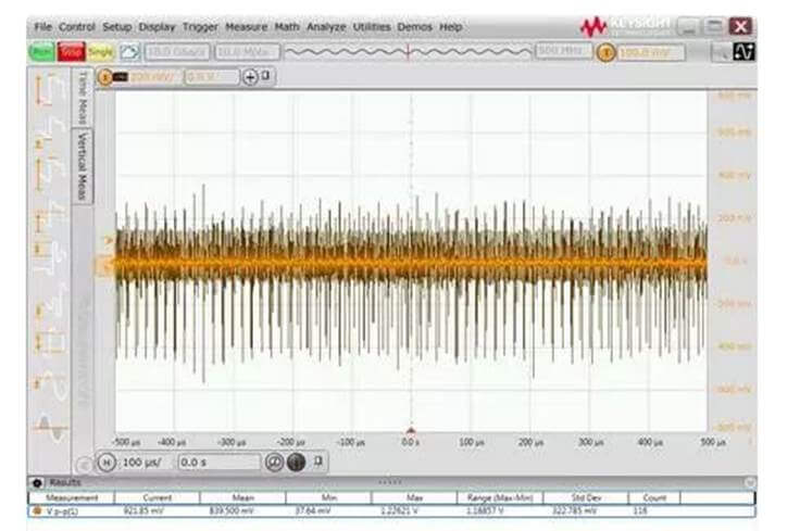
01 Root Cause Analysis & Troubleshooting
The issue of excessively large power supply ripple measurements is usually related to the probes used and the front-end connection method. First, the user’s probe connection was checked, revealing that a long alligator clip ground wire was used, as shown in the left figure below, and the grounding point was clipped onto a mounting screw on the board, resulting in a relatively large ground loop. Because a large ground loop picks up more spatial electromagnetic radiation noise generated by the switching power supply as well as ground loop noise, it was replaced with a short ground spring pin, as shown in the right figure below.
After actual testing, it was found that the measured peak-to-peak ripple and noise was greatly improved, as shown in the figure below. However, the peak-to-peak value of the ripple noise was still over 40mV, which was still significantly different from the <20mV nominal value specified by the switching power supply manufacturer.
Further checking the model of the probe used by the user revealed that a standard 10:1 passive probe included with the oscilloscope was being used, as shown in the figure below.
A 10:1 probe attenuates the measured signal by 10 times before feeding it into the oscilloscope, and the oscilloscope then mathematically amplifies the measured signal by 10 times. The advantage of this type of probe is that its matching circuit boosts the probe bandwidth up to several hundred MHz and extends the oscilloscope’s measurement range. However, it is not particularly favorable for small signal measurements. If the amplitude of the measured signal is small to begin with, attenuating it by 10 times may cause it to be submerged in the noise floor of the oscilloscope. Even with a 10x mathematical amplification, the signal-to-noise ratio itself is not improved. Therefore, for power supply ripple and noise measurements, probes with a small attenuation ratio, such as 1:1 probes, should be used whenever possible. Thus, a 1:1 passive probe was located. Although this 1:1 passive probe has a lower bandwidth (usually tens of MHz), its small attenuation ratio makes it very suitable for small signal testing.
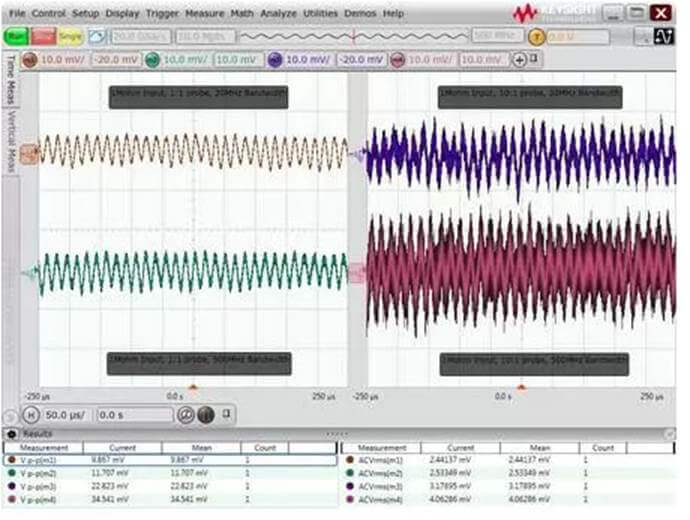
The figure below shows the comparative test results between the 1:1 passive probe and the 10:1 probe under different bandwidth limits. It can be seen that after using the 1:1 probe and setting a 20MHz bandwidth limit, the measured peak-to-peak ripple noise was less than 10mV, which is far better than the test result of the 10:1 probe. Clear ripple waveforms can be observed from the 1:1 probe test results, satisfying the user’s expectation of power supply ripple noise <20mV. In addition, we can also see that the bandwidth limit contributes to improving the peak-to-peak noise level.

02 Key Takeaways for Ripple Measurement
This case study highlights a classic pitfall in power supply ripple testing. By using a short ground connection, switching to a probe with a low attenuation ratio, and enabling the bandwidth limit function, the ripple noise test results were significantly improved. Generally speaking, the main factors affecting power supply ripple test results, in order of importance, include:
- Length of front-end connecting wires and ground loop: A long ground loop picks up more electromagnetic radiation from the switching power supply and ground noise; therefore, ground connections should be kept as short as possible.
- Probe attenuation ratio: A probe with a high attenuation ratio makes small signals even weaker, potentially submerging them in the oscilloscope’s noise floor. Therefore, probes with a 1:1 attenuation ratio should be used whenever possible.
- Bandwidth limit: Much of the electromagnetic noise and oscilloscope noise floor is broadband. Setting an appropriate bandwidth limit can filter out extraneous noise. A 20MHz bandwidth limit is commonly used in power supply ripple noise testing, though some chips may require testing up to 80MHz or 200MHz.
- Measurement range: Power supply ripple tests are usually conducted under small scale settings (such as 10mV/div or 20mV/div). The larger the scale, the higher the oscilloscope’s noise floor. However, because some oscilloscopes have limited offset ranges, they may not be able to pull the DC voltage signal back near the center of the screen for measurement at small scale settings. As a result, the AC coupling function of the oscilloscope is often used to isolate the DC component before testing ripple noise.
- Input impedance: Many oscilloscopes provide a choice between 50-ohm and 1M-ohm input impedance, and the oscilloscope’s noise floor is generally lower at 50-ohm input impedance. However, when connected to most passive probes, the oscilloscope automatically switches the impedance to 1M-ohm; it can only be set to 50-ohm input impedance when connected to active probes or coaxial cables.
Before conducting actual tests, a good practice is to first check the system noise floor under the current equipment and settings. The five waveforms in the figure below show the noise floor results of a 500MHz S-series oscilloscope using different probes and bandwidth settings. From top to bottom, the waveforms correspond to: 50-ohm input impedance, 1:1 probe, 500MHz bandwidth; 1M-ohm input impedance, 1:1 probe, 20MHz bandwidth; 1M-ohm input impedance, 1:1 probe, 500MHz bandwidth; 1M-ohm input impedance, 10:1 probe, 20MHz bandwidth; and 1M-ohm input impedance, 10:1 probe, 500MHz bandwidth. The peak-to-peak noise floor ranges from less than 1mV to nearly 30mV, demonstrating the importance of probe, bandwidth, and input impedance settings during testing.
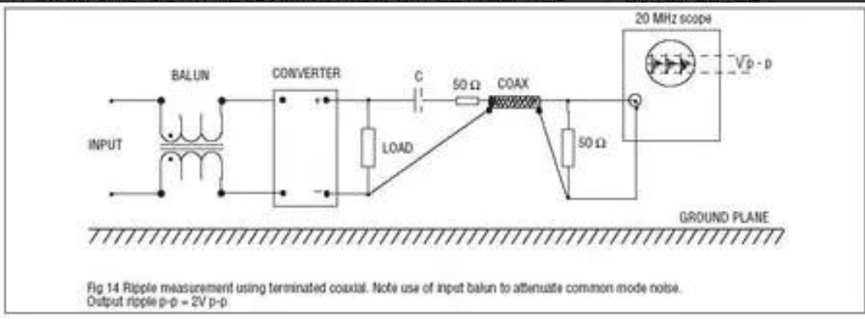
If a suitable low-attenuation probe is not readily available, a DIY probe can be made using a 50-ohm coaxial cable as shown below. In practice, one end of the cable is connected to the oscilloscope with the oscilloscope set to 50-ohm input impedance; the other end of the cable is stripped, with the shield soldered to the ground of the circuit under test, and the center conductor connected to the power signal via a DC-blocking capacitor. The advantages of this method are low cost and low attenuation ratio, while its disadvantages are poor consistency and hard-to-control parameters for the DC-blocking capacitor and bandwidth. In recent years, oscilloscope manufacturers have also introduced probes specially designed for power supply ripple testing, combining low attenuation ratio (1.1:1), high bandwidth (hardware 2GHz, software-configurable bandwidth limits), impedance matching that balances measurement needs and noise (the probe itself has a DC input impedance of 50k ohms, but the oscilloscope end is a 50-ohm input impedance spectrum), short ground wires (providing a soldering front-end with very low loop inductance), large offset range (up to ±24V), and the capability to simultaneously test ripple and DC voltage, making them suitable for users with high requirements for power supply ripple measurement.