Introduction
Even experienced electronics engineers can overlook design decisions that appear minor during development but later result in higher manufacturing costs, excessive power consumption, reduced reliability, or poor signal integrity.
As embedded systems, high-speed digital interfaces, FPGAs, and multilayer PCBs become increasingly complex, successful hardware design depends not only on selecting the right components but also on making sound engineering trade-offs throughout the design process.
This article summarizes 29 common design mistakes and reframes them as practical, nuanced engineering guidelines involving component selection, PCB layout, embedded software, power optimization, and signal integrity. Each item details why the mistake occurs and how experienced engineers evaluate the underlying trade-offs.
1. Cost Optimization
Common Mistake 1:
“Which color should I choose for the panel indicator LED? I personally like blue, so I’ll use that.”
Correct Approach:
Historically, blue LEDs were significantly more expensive than standard red, green, yellow, or orange variants. However, in modern surface-mount technology (SMT) packages, blue LEDs have become widely commoditized, and pricing differences are often minimal. Rather than viewing LED color selection purely through a general cost rule, engineers should treat it as a component availability, sourcing, and supply-chain consideration. Unless an application specifically dictates a color scheme (such as standardized status indicators), choosing standard, high-volume colors remains a reliable way to ensure supply stability and minimal BOM impact.
Common Mistake 2:
“The value of these pull-up or pull-down resistors doesn’t seem critical. Let’s just use a nice round 5 kΩ.”
Correct Approach:
Labeling 5 kΩ as a non-standard resistor is somewhat misleading, but standard preferred values such as 4.99 kΩ (1% series) and 5.1 kΩ (5% series) are far more commonly stocked today. Modern 1% resistors are frequently manufactured in extremely high volumes and carry little to no cost premium compared to legacy high-tolerance parts. Nevertheless, selecting widely stocked standard values (like 4.7 kΩ or 10 kΩ) avoids unnecessary BOM fragmentation. Quality remains paramount—purchasing components from reliable, authorized distributors is essential to guarantee long-term parametric consistency.
Common Mistake 3:
“This simple logic could be built with 74XX logic gates, but using a CPLD looks more advanced.”
Correct Approach:
A discrete 74XX logic IC typically costs a fraction of a CPLD or small FPGA. Beyond increasing bill-of-materials costs, adding programmable logic increases design overhead, manufacturing complexity, programming, testing, and documentation requirements. Unless reconfigurability or higher integration density is truly required, using discrete logic ICs is usually the most economical and straightforward choice.
Common Mistake 4:
“This PCB isn’t very demanding. I’ll use narrow traces and let the autorouter do the work.”
Correct Approach:
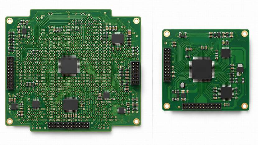
Autorouting has advanced significantly with modern EDA tools, especially for dense digital designs, BGAs, and memory interfaces. However, poor routing strategies—whether generated manually or automatically—can increase PCB layer counts, expand board area, create unnecessary vias, and reduce yield. Rather than assuming autorouting inherently increases manufacturing costs, engineers should evaluate routing quality. Well-constrained autorouting or skilled manual layout both aim to optimize board space, minimize via counts, and ensure high manufacturing yield.
Common Mistake 5:
“Our system has high performance requirements, so every chip—including the CPU, FPGA, and memory—should be the fastest version available.”
Correct Approach:
Not every subsystem in a high-speed design requires maximum speed grade components. Over-specifying every component dramatically increases costs while potentially introducing unwanted thermal and signal integrity challenges due to faster edge rates. Components should be selected according to the actual timing and performance requirements of each functional block.
Common Mistake 6:
“As long as the software is stable, it doesn’t matter if the code is longer or less efficient.”
Correct Approach:
Hardware capability directly affects product cost. Optimizing software routines can allow the system to run on a processor with a lower clock speed or smaller internal flash/RAM, leading to significant unit-cost savings across mass production. The same principle applies to logic designs in CPLDs and FPGAs—efficient RTL implementation enables smaller, lower-cost target devices.
2. Reliability Design
Common Mistake 7:
“This board has passed long-term testing and small-batch production. There’s no need to keep checking the chip datasheet.”
Correct Approach:
Designs must strictly adhere to component datasheet limits, including voltage ratings, I/O tolerances, thermal constraints, and timing margins. A design that operates successfully in prototypes may fail in production if a component vendor updates a silicon revision or process node—even if the part remains fully within published specifications. Designing conservatively within official datasheet boundaries ensures long-term operational margin and component inter-compatibility.
Common Mistake 8:
“If users make mistakes while operating the product, it’s not my responsibility.”
Correct Approach:
Robust designs anticipate user error, such as incorrect cable connections, out-of-range input signals, or improper sequence handling. Hardware protection mechanisms—such as overvoltage protection, ESD diodes, and reverse-polarity protection—prevent user mistakes from causing permanent equipment damage or system lockups.
Common Mistake 9:
“If the connected external board malfunctions, it’s not my fault.”
Correct Approach:
External interfaces should be designed with sufficient isolation and fault tolerance. Failures on peripheral boards or external cabling should affect only the localized interface rather than propagating to damage or shut down the primary system. Once the external fault is resolved, the interface should recover automatically.
Common Mistake 10:
“This circuit is safe as long as the software follows the intended sequence.”
Correct Approach:
Software bugs and execution stalls are inevitable. If firmware crashes or enters an unexpected state, hardware protection (such as current limits, hardware interlocks, and thermal cutoffs) must prevent physical damage to the system. Safe hardware behavior must be guaranteed independently of software execution state.
3. System Efficiency
Common Mistake 11:
“Should I use interrupts or polling? Interrupts must be faster.”
Correct Approach:
Interrupts deliver low-latency response for sporadic events, but high-frequency interrupts can introduce substantial context-switching overhead that degrades overall CPU throughput. For extremely frequent or high-throughput data streams, a controlled polling or DMA-based mechanism often yields higher net execution efficiency.
Common Mistake 12:
“The CPU is running at 70% utilization. Upgrading from 100 MHz to 200 MHz will solve the problem.”
Correct Approach:
System bottlenecks are often tied to memory bandwidth, bus contention, or I/O access delays rather than raw CPU clock frequency. Doubling processor clock speed yields little benefit if the CPU spends significant cycles idling during external memory accesses.
Common Mistake 13:
“Increasing the CPU cache size will definitely improve performance.”
Correct Approach:
Cache memory provides significant acceleration only when data structures display spatial and temporal locality. In streaming architectures or low-latency communication buffers, caching unneeded regions can lead to cache thrashing. Modern architectures require deliberate cache management and code structuring to realize performance benefits.
Common Mistake 14:
“The default memory timing provided by the manufacturer is good enough.”
Correct Approach:
Default BSP memory timing configurations are usually set conservatively to guarantee startup across all conditions. Tuning memory controller parameters based on actual bus frequencies, trace delays, and device access characteristics can unlock significant system throughput.
Common Mistake 15:
“This CPU has a DMA controller, so using DMA must always be faster than software.”
Correct Approach:

DMA transfers carry setup and descriptor overhead. For small data payloads, direct software register transfers are often faster and consume fewer system resources than initializing a DMA channel. DMA is primarily advantageous when handling larger, continuous data blocks.
Common Mistake 16:
“One CPU isn’t enough. Using two CPUs should double the processing power.”
Correct Approach:
Multiprocessing efficiency depends heavily on workload partitioning, inter-core communication, and shared resource contention. Without efficient software architecture and low-overhead synchronization, the synchronization burden can consume a large portion of the secondary processor’s capacity.
4. Low-Power Design
Common Mistake 17:
“Let’s add pull-up or pull-down resistors to all these bus signals. It feels safer.”
Correct Approach:
Unnecessary pull-up or pull-down resistors on actively driven, multi-bit buses can create continuous DC current paths when signals are held in low or high states. Across modern wide buses, this practice can unnecessarily waste significant power, degrading thermal performance and system efficiency.
Common Mistake 18:
“Our system runs on 220 VAC, so power consumption isn’t a concern.”
Correct Approach:
Low-power design is vital regardless of the primary power source. Lower power dissipation reduces operating temperatures, eliminates expensive heatsinks or forced-air cooling, minimizes thermal stress on adjacent components, and extends long-term system reliability.
Common Mistake 19:
“These small ICs consume very little power, so there’s no need to worry about them.”
Correct Approach:
An IC’s total power consumption includes both static internal draw and dynamic current driven into external loads. For example, logic buffers like an ABT16244 draw minimal quiescent current, but driving multiple heavily loaded low-impedance lines can result in significant current draw under peak load. Note that while theoretical maximum ratings might yield high worst-case numbers (e.g., up to 960 mA), actual operating currents in real-world applications are typically much lower and depend directly on line loading, switching activity, and duty cycle.
Common Mistake 20:
“What should we do with the unused CPU or FPGA I/O pins? Let’s leave them floating for now.”
Correct Approach:
Unused CMOS input pins should never be left floating, as noise can cause them to drift between logic levels, triggering shoot-through currents in the input stages. However, configuring unused pins as outputs is not universally applicable. Modern MCU and FPGA vendors provide specific, device-dependent termination guidelines (e.g., internal pull-ups, pull-downs, or software configuration). Following the manufacturer’s recommended practices for the specific component family is the safest approach.
Common Mistake 21:
“This FPGA still has plenty of unused logic resources, so let’s make full use of them.”
Correct Approach:
Dynamic power in FPGAs is directly proportional to clock rates and internal logic switching activity. Instantiating unneeded logic blocks or allowing unused clock domains to toggle unnecessarily increases dynamic power consumption and thermal load.
Common Mistake 22:
“This memory chip has several control signals. Since we only need OE and WE, let’s tie the chip select (CS) permanently low for faster access.”
Correct Approach:
Permanently asserting Chip Select (CS) keeps the internal memory peripheral fully active, preventing the device from entering low-power standby modes. CS should be gated properly so the memory enters standby whenever it is not actively being accessed.
Common Mistake 23:
“Power optimization is purely a hardware responsibility. Software doesn’t matter.”
Correct Approach:
Hardware establishes the physical power floor, but software dictates operating state transitions. Effective power optimization relies on software managing low-power sleep modes, clock gating, dynamic frequency scaling, and efficient peripheral scheduling.
Common Mistake 24:
“These signals all show overshoot. If we improve impedance matching enough, we can eliminate it completely.”
Correct Approach:
Minor overshoot is common in digital interfaces. Attempting to achieve perfect impedance matching across all states can lead to over-termination, which degrades edge rise times, increases power dissipation, and reduces noise margins. The objective is to keep signal transitions clean and overshoot within component specification limits.
5. Signal Integrity
Common Mistake 25:
“We’ve already completed signal integrity simulations, so the design must be reliable.”
Correct Approach:
Simulation models provide critical insight but depend on assumed parameters. Real-world factors such as manufacturing tolerances, PCB dielectric variations, power supply noise, and complex multi-line simultaneous switching noise (SSN) require adequate engineering design margins beyond simulation results.
Common Mistake 26:
“More decoupling capacitors always mean a cleaner power supply.”
Correct Approach:
Power delivery network (PDN) performance depends on low impedance across target frequencies, which requires selecting proper capacitance values, package sizes, and low-inductance placement strategies. Indiscriminately adding capacitors increases BOM cost, consumes PCB area, and can introduce unwanted power-on inrush currents.
Common Mistake 27:
“Since these are digital signals, the faster the edge transition, the better.”
Correct Approach:
Extremely fast rise times introduce high-frequency harmonic content that increases electromagnetic radiation (EMI), ringing, and crosstalk. Slew rates should be kept only as fast as necessary to meet timing requirements, utilizing programmable drive strength or series termination to soften edges where appropriate.
Common Mistake 28:
“Signal termination is complicated. How can we match signals correctly?”
Correct Approach:
Impedance discontinuities along transmission lines cause reflections when signal transition times are short relative to propagation delay. Point-to-point routing is generally good practice to minimize stubs and discontinuities. However, notable exceptions exist—such as DDR fly-by topologies and intentionally designed multidrop buses. Engineers should apply point-to-point routing where appropriate while understanding topology exceptions required by specific interface standards.
Common Mistake 29:
“A 100 MHz data bus is definitely a high-speed signal, but an 8 kHz clock isn’t important.”
Correct Approach:
Signal integrity concerns are driven by edge rates (rise/fall times) rather than repeating clock frequencies. A low-frequency clock with sharp edges is vulnerable to crosstalk and ringing. Because clocks serve as timing references for the system, clean, monotonic clock transitions are vital regardless of operating frequency.
Key Takeaways
Many hardware challenges stem from treating nuanced engineering design trade-offs as absolute rules. By framing design decisions around system-level constraints—such as component availability, device-specific vendor guidance, realistic operating conditions, and topology requirements—engineers can balance performance, manufacturability, cost targets, and long-term reliability effective