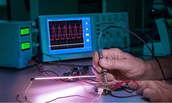
Hardware Inspection Before Powering On
When a circuit board is completely soldered, when checking whether the circuit board can work normally, usually do not supply power directly to the circuit board, but proceed according to the following steps, ensuring there is no problem in each step before powering on.
- Whether connections are correct. Checking the schematic is very critical. The first key focus of checking is whether the labels of the chip’s power supply and network nodes are correct, while also paying attention to whether there is overlap in the network nodes. Another focus is the component packaging, the packaging model, and the packaging pin sequence; packaging cannot use the top view, remember! Especially for non-through-hole packaging. Check if connections are correct, including wrong lines, missing lines, and extra lines. There are usually two methods for wire checking: 1) Check the installed circuits according to the circuit diagram, and check the installed circuits one by one according to the circuit connections in a certain order; 2) Follow the actual circuits and compare them with the schematic diagram, taking a component as the center for wire checking. Check the connection of each component pin at once, and check whether each destination exists on the circuit diagram. To prevent errors, lines that have already been checked should usually be marked on the circuit diagram, preferably tested with the buzzer of a pointer multimeter’s ohm range, directly measuring the component pins, so that bad connections can be discovered at the same time.
- Whether the power supply is short-circuited. Do not power on before debugging, use a multimeter to measure the input impedance of the power supply, which is a mandatory step! If the power supply is short-circuited, it will cause the power supply to burn out or even worse consequences. When involving the power supply part, a 0-ohm resistor can be used as a debugging method. Do not solder the resistor before powering on, check that the voltage of the power supply is normal, and then solder the resistor onto the PCB to supply power to the subsequent units, so as to avoid burning the chips of subsequent units due to abnormal power supply voltage upon power-on. Increase protection circuits in the circuit design, such as using components like resettable fuses.
- Component installation status. It is mainly to check polarized components, such as light-emitting diodes, electrolytic capacitors, rectifier diodes, etc., and whether the pins of the transistors correspond. For transistors, the pin arrangements of different manufacturers for the same function are also different, so it is best to test them with a multimeter.
Do open-circuit and short-circuit tests first to ensure that no short-circuit phenomenon occurs after powering on. If test points are set up well, it can achieve twice the result with half the effort. The use of 0-ohm resistors is also sometimes beneficial for high-speed circuit testing. After the above hardware inspections before powering on are completed, power-on detection can begin.
Power-on Detection
- Power-on observation: Do not rush to measure electrical indicators after powering on, but observe whether there are abnormal phenomena in the circuit, such as whether there is smoking, whether there is abnormal smell, touch the outer packaging of the integrated circuit with your hand to see if it is hot, etc. If an abnormal phenomenon occurs, the power supply should be turned off immediately, and then powered on after troubleshooting.
- Static debugging: Static debugging generally refers to DC testing conducted under the condition of no input signal or only a fixed level signal. A multimeter can be used to measure the potential of each point in the circuit. By comparing it with the theoretical estimated value and combining it with the analysis of circuit principles, it is judged whether the DC working state of the circuit is normal, so as to timely discover components that are already damaged or in a critical working state. By replacing components or adjusting circuit parameters, the DC working state of the circuit meets the design requirements.
- Dynamic debugging: Dynamic debugging is conducted on the basis of static debugging. Add a suitable signal to the input end of the circuit, and sequentially detect the output signals of each test point according to the signal flow direction. If any abnormal phenomenon is found, analyze its cause, eliminate the fault, and then continue debugging until the requirements are met. You cannot rely on feeling during the testing process; you must always use instruments to observe. When using an oscilloscope, it is best to place the signal input mode of the oscilloscope in the “DC” gear. Through the DC coupling mode, the AC and DC components of the measured signal can be observed at the same time. Through debugging, finally check whether the various indicators of the functional blocks and the whole machine (such as signal amplitude, waveform shape, phase relationship, gain, input impedance, and output impedance, etc.) meet the design requirements, and if necessary, further put forward reasonable corrections to the circuit parameters.
Other Work in Electronic Circuit Debugging
- Determine test points: Draft debugging steps and measurement methods according to the working principle of the system to be adjusted, determine the test points, and mark the locations on the drawings and the board, make debugging data record tables, etc.
- Set up the debugging workbench: The workbench is equipped with the required debugging instruments, and the arrangement of instruments should be convenient to operate and observe. Special tip: During production and debugging, the workbench must be arranged clean and tidy.
- Select measuring instruments: For hardware circuits, measuring instruments should be selected for the system under adjustment, and the accuracy of the measuring instruments should be superior to the system under test; for software debugging, microcomputers and development devices should be equipped.
- Debugging sequence: The debugging sequence of electronic circuits is generally carried out according to the signal flow direction, taking the output signal of the previously debugged circuit as the input signal of the next stage, creating conditions for final joint debugging.
- Overall debugging: Digital circuits implemented by programmable logic devices should complete the input, debugging, and downloading of programmable logic device source files, and connect the programmable logic devices and analog circuits into a system for overall debugging and results testing. During the debugging process, carefully observe and analyze the experimental phenomena, and make records to ensure the integrity and reliability of the experimental data.
Precautions in Circuit Debugging
Whether the debugging results are correct depends to a large extent on the correctness of the measurement and the measurement accuracy. In order to ensure the test results, test errors must be reduced and test accuracy must be improved. For this purpose, the following points need to be paid attention to:
- Correctly use the grounding terminal of the test instrument. When using an electronic instrument whose ground terminal is connected to the chassis for testing, the grounding terminal of the instrument should be connected together with the grounding terminal of the amplifier, otherwise the interference introduced by the instrument chassis will not only change the working state of the amplifier, but also cause errors in the test results. According to this principle, when debugging the emitter bias circuit, if Vce needs to be tested, the two ends of the instrument should not be directly connected to the collector and emitter, but Vc and Ve should be measured to ground respectively, and then subtract the two. If a multimeter powered by dry batteries is used for testing, since the two input terminals of the meter are floating, it is allowed to cross-connect directly between the test points.
- The input impedance of the instrument used to measure voltage must be far greater than the equivalent impedance at the measured location. If the input impedance of the testing instrument is small, it will cause shunting during measurement, bringing a large error to the test results.
- The bandwidth of the testing instrument must be greater than the bandwidth of the circuit under test.
- Correctly select test points. When the same testing instrument is used for measurement, if the measurement points are different, the error caused by the internal resistance of the instrument will be completely different.
- The measurement method must be convenient and feasible. When it is necessary to measure the current of a certain circuit, generally measure the voltage instead of the current as much as possible, because measuring voltage does not need to modify the circuit. If you need to know the current value of a certain branch, you can obtain it through conversion by measuring the voltage across the resistor on that branch.
- During the debugging process, not only must you observe and measure carefully, but you must also be good at recording. The recorded contents include experimental conditions, observed phenomena, measured data, waveforms, and phase relationships, etc. Only when a large number of reliable experimental records are compared with theoretical results can problems in circuit design be discovered and design solutions perfected.
Troubleshooting During Debugging
Carefully look for the cause of the fault, and never dismantle the circuit and reinstall it as soon as a fault cannot be solved. Because if it is a principle problem, even reinstalling it will not solve the problem.

- General methods for fault inspection For a complex system, it is not easy to accurately find faults among a large number of components and lines. The general fault diagnosis process starts from the fault phenomenon, through repeated testing, making analysis and judgment, and gradually finding the fault.
- Fault phenomena and causes of faults
- Common fault phenomena: The amplifier circuit has no input signal but has an output waveform. The amplifier circuit has an input signal but no output waveform, or the waveform is abnormal. The series regulated power supply has no voltage output, or the output voltage is too high to be adjusted, or the voltage regulation performance deteriorates, and the output voltage is unstable, etc. The oscillation circuit does not generate oscillation, the counter waveform is unstable, and so on.
- Causes of faults: After a finalized product is used for a period of time, a fault occurs, which may be due to component damage, short circuits and open circuits in lines, or changes in conditions, etc.
- General methods for checking faults
- Direct observation method: Check whether the selection and use of the instruments are correct, and whether the grade and polarity of the power supply voltage meet the requirements; whether the pins of polarized components are connected correctly, and whether there are wrong connections, missing connections, and mutual touching. Whether the wiring is reasonable; whether the printed board has short lines or broken lines, and whether resistors and capacitors are scorched or cracked, etc. Power on and observe whether the components are hot or smoking, whether the transformer has a burning smell, whether the filaments of electron tubes and oscilloscope tubes are bright, and whether there is high-voltage sparking, etc.
- Use a multimeter to check the static working point: The power supply system of electronic circuits, the DC working state of semiconductor transistors and integrated blocks (including component pins, power supply voltage), and the resistance values in lines can all be determined with a multimeter. When the measured value differs greatly from the normal value, the fault can be found through analysis. Incidentally, the static working point can also be determined using the “DC” input mode of an oscilloscope. The advantage of using an oscilloscope is high internal resistance, being able to see the DC working state, the signal waveform on the measured point, and possible interference signals and noise voltage at the same time, which is more conducive to analyzing faults.
- Signal tracing method: For various complex circuits, a signal with a certain amplitude and appropriate frequency can be connected to the input end (for example, for a multi-stage amplifier, a 1000 Hz sine signal can be connected to its input end), and use an oscilloscope from the front stage to the back stage (or vice versa) to observe the changes in waveform and amplitude stage by stage. If any stage is abnormal, the fault is in that stage.
- Comparison method: When a certain circuit is suspected to have a problem, the parameters of this circuit can be compared one by one with the same normal parameters (or theoretically analyzed current, voltage, waveforms, etc.) to find the abnormal conditions in the circuit, and then analyze and judge the fault point.
- Component replacement method: Sometimes the fault is relatively hidden and cannot be seen at a glance. If you have an instrument of the same model as the faulty instrument at hand at this time, you can replace the parts, components, plug-in boards, etc., in the instrument with the corresponding parts in the faulty instrument, so as to narrow down the fault scope and find the fault source.
- Bypass method: When there is a parasitic oscillation phenomenon, an appropriate capacity capacitor can be used to select an appropriate inspection point, and the capacitor can be temporarily cross-connected between the inspection point and the reference ground point. If the oscillation disappears, it indicates that the oscillation is generated near this or in the preceding circuit. Otherwise, it is behind, and move the inspection point further to find it. The bypass capacitor should be appropriate, not too large, as long as it can eliminate harmful signals well.
- Short-circuit method: It is a method of finding faults by temporarily short-circuiting a part of the circuit. The short-circuit method is most effective for checking open-circuit faults. However, note that the short-circuit method cannot be applied to the power supply (circuit).
- Open-circuit method: The open-circuit method is most effective for checking short-circuit faults. The open-circuit method is also a method to gradually narrow down the range of suspected fault points. For example, a regulated power supply causes an excessively large output current due to being connected to a faulty circuit. We adopt the method of sequentially disconnecting a certain branch of the circuit to check the fault. If the current returns to normal after disconnecting that branch, the fault occurs in this branch.
In actual debugging, there are various methods to find the cause of faults. The above only lists several commonly used methods. The use of these methods can find the fault point with one method for simple faults, but for more complex faults, multiple methods need to be used to complement and cooperate with each other to find the fault point. In general, the conventional practice for finding faults is:
- Use the direct observation method to eliminate obvious faults.
- Then use a multimeter (or oscilloscope) to check the static working point.
- The signal tracing method is a universally applicable, simple, and intuitive method for various circuits, which is widely applied in dynamic debugging.